Ce este o sită din sârmă profilată?
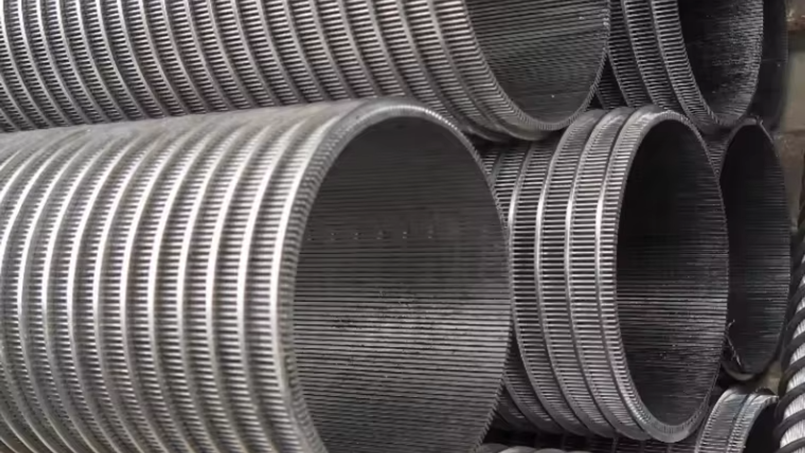
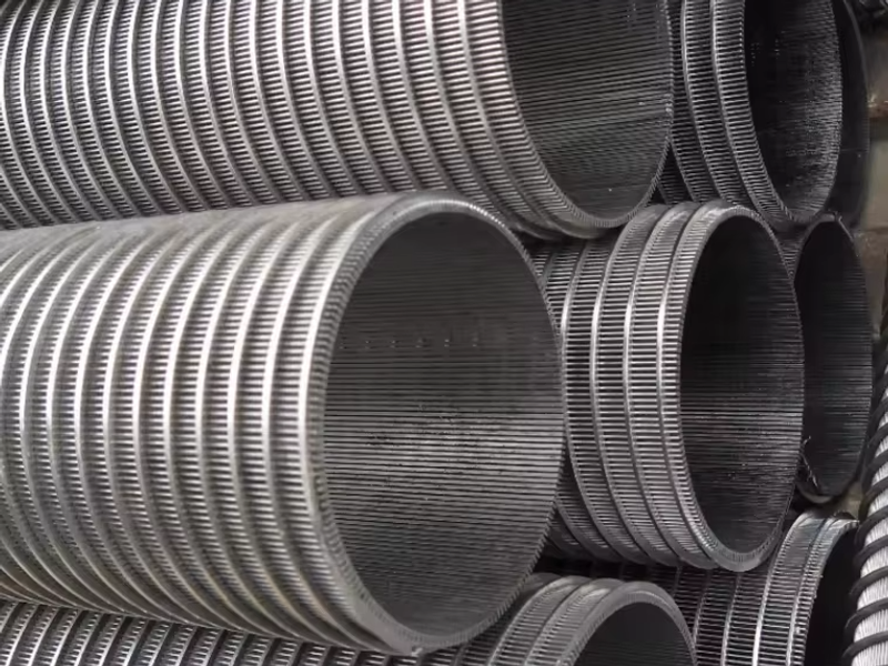
O sită din sârmă profilată — numită și sită Vee-wire, sită cu sârmă profilată sau sită Johnson (denumirea comercială originală) — este un element de filtrare realizat din sârmă triunghiulară (în formă de V) din oțel inoxidabil, înfășurată elicoidal în jurul unor tije de suport longitudinale și sudată în fiecare punct de contact dintre sârmă și tijă. Spațiul continuu lăsat între spirele adiacente ale sârmei profilate se numește fantă, iar lățimea acestui spațiu — dimensiunea fantei — este cel mai important parametru de proiectare al întregii site.
KAIFIL fabrică site din sârmă profilată cu deschideri standard ale fantelor de la 0.1 mm la 3.0 mm, cu deschideri personalizate disponibile în afara acestui interval, la cerere. Dimensiunea fantei controlează retenția particulelor printr-o relație directă, măsurabilă: o fantă de 0.25 mm reține marea majoritate a particulelor mai mari de aproximativ 0.3 mm într-o formațiune naturală de nisip, deoarece granulele ușor mai mari decât deschiderea formează o punte peste fața fantei și creează un pat filtrant natural stabil. Suprafața deschisă — raportul dintre lățimea fantei și (lățimea fantei + lățimea superioară a sârmei) — variază de obicei de la aproximativ 11% pentru o fantă fină de 0.25 mm pe o sârmă profilată de 2.0 mm până la aproximativ 50% pentru o fantă de 2.0 mm, iar capacitatea de debit crește aproximativ proporțional.
Deoarece fanta se îngustează spre suprafața exterioară și se lărgește spre interior, sitele wedge wire sunt în mod inerent cu autocurățare și anti-colmatare, motiv pentru care domină aplicațiile exigente de separare lichid-solid: puțuri de apă și puțuri de desecare, prize de apă de suprafață și site pentru puțuri, controlul nisipului, cernerea mineralelor și agregatelor, procesarea alimentelor și băuturilor, tratarea apelor uzate și filtrarea industrială. Pentru o comparație tehnică a celor două geometrii dominante de sită, consultați ghidul nostru despre site din sârmă profilată (wedge wire) vs. plasă țesută pentru aplicații în puțuri de apă.
Cum funcționează dimensiunea fantei: Fizica retenției
Lățimea fantei determină cea mai mare particulă care poate trece prin sită. Orice granulă a cărei dimensiune minimă este mai mare decât lățimea fantei este reținută la suprafața sitei; orice este mai mic trece în fluxul de curgere.
Mecanismul care face ca dimensionarea fantei să fie tolerantă în formațiunile reale este formarea de punți. Când mai multe particule, fiecare puțin mai mare decât deschiderea, ajung la aceeași fantă, se blochează una în cealaltă și formează un arc stabil pe suprafața fantei. Această punte naturală reține fracțiunea mai grosieră, permițând în același timp trecerea particulelor fine, și construiește treptat o turtă de filtrare stratificată. Consecința practică este că o sită wedge wire reține particulele la și chiar sub dimensiunea nominală a fantei sale, nu doar pe cele strict peste aceasta. În scopuri de proiectare, se poate conta pe o fantă de 0.25 mm pentru a reține o formațiune de nisip mediu, chiar dacă valoarea D50 a acelei formațiuni poate fi doar marginal mai mare decât deschiderea.
Deoarece fanta este un canal continuu mai degrabă decât un model de orificii discrete, fiecare particulă care se deplasează de-a lungul suprafeței sitei întâlnește o deschidere identică în fiecare punct al traseului său. Nu există colțuri drepte și nici deschideri „la limită”, astfel încât retenția este mult mai uniformă decât pe o țeavă perforată sau o plasă țesută, și nu există nicio zonă în care o particulă de dimensiune intermediară să se poată bloca și să obstrucționeze permanent fluxul.
Selecția dimensiunii fantei vs. Analiza dimensiunii particulelor
Alegerea fantei corecte începe cu cunoașterea a ceea ce rețineți. Datele de intrare standard sunt o analiză prin cernere a formațiunii sau a materialului de alimentare, reprezentată grafic sub forma unei curbe granulometrice (distribuția dimensiunii particulelor). Pe baza acestei curbe, inginerii citesc patru dimensiuni caracteristice:
- D10 — dimensiunea la care 10% din material, în greutate, este mai fin
- D30 — dimensiunea la care 30% este mai fin
- D50 — dimensiunea medie a granulei (50% mai fin)
- D60 — dimensiunea la care 60% este mai fin
Coeficientul de uniformitate este Cu = D60 / D10. Acesta indică cât de bine sortat este materialul: un Cu scăzut (sub aproximativ 3) înseamnă un nisip uniform; un Cu ridicat înseamnă un material bine gradat, mixt. Cu cât Cu este mai mare, cu atât fanta trebuie să fie mai fină în raport cu dimensiunea medie a granulelor, deoarece o formațiune bine gradată conține o fracțiune semnificativă de particule fine care trebuie controlată pentru a preveni pomparea nisipului.
Trei abordări sunt utilizate pe scară largă în industria puțurilor de apă și a deshidratării:
- Reținerea a 40–60% din greutate. Dimensionați fanta astfel încât 40–60% din formațiune să fie reținută de sită. Pentru un nisip uniform, acest lucru plasează de obicei fanta între D30 și D50.
- Regula D30 pentru nisipuri uniforme (Cu < 3). Selectați o fantă aproximativ egală cu D30; sita va reține aproximativ jumătate din formațiune și va lăsa să treacă particulele fine curate.
- Regula D10 pentru formațiuni neuniforme (Cu ≥ 5). Selectați o fantă mai apropiată de D10, astfel încât fracțiunea mai fină să fie de asemenea controlată și să se poată forma rapid o punte stabilă.
Tabelul de mai jos rezumă punctele de pornire tipice utilizate în cadrul proiectelor KAIFIL de puțuri de apă și deshidratare.
Tabelul 1 — Dimensiuni recomandate ale fantelor în funcție de tipul de formațiune
| Tip formațiune | Interval tipic al dimensiunii granulelor | Dimensiune recomandată a fantei | Aplicație tipică |
|---|
| Silt / nisip foarte fin | 0.05–0.15 mm | 0.1–0.2 mm | Filtre cu nisip lent; puțuri de irigații |
| Nisip fin | 0.15–0.25 mm | 0.2–0.3 mm | Puțuri domestice și municipale mici |
| Nisip mediu | 0.25–0.5 mm | 0.3–0.5 mm | Puțuri de alimentare municipale și industriale |
| Nisip grosier | 0.5–1.0 mm | 0.5–1.0 mm | Puțuri cu debit mare; desecare |
| Pietriș / strat de pietriș | 1.0–3.0 mm | 1.0–3.0 mm | Puțuri cu filtru de pietriș; drenaj; site de admisie |
Selecția fantei este întotdeauna un echilibru: o fantă prea fină restricționează debitul și se înfundă cu particule fine; o fantă prea grosieră permite trecerea nisipului din formațiune și deteriorează pompele și echipamentele din aval. Fanta corectă permite formațiunii să se auto-sorteze la suprafața sitei.
Lățimea fantei, suprafața activă și capacitatea de debit
Suprafața activă este fracțiunea din suprafața sitei care este efectiv deschisă pentru curgere. Pentru o sită wedge wire, aceasta se calculează astfel:
Suprafață activă (%) = Lățime fantă / (Lățime fantă + Lățime superioară sârmă) × 100
Suprafața activă este cel mai important factor determinant al performanței hidraulice. Dublarea lățimii fantei, menținând neschimbate toate celelalte dimensiuni, dublează aproximativ suprafața activă și, prin urmare, debitul pe care o anumită suprafață a sitei îl poate transporta la aceeași viteză de intrare. Consecința practică este că dimensiunea "corectă" a fantei nu este doar o decizie de retenție — este o decizie de debit.
Tabelul 2 — Dimensiunea fantei vs. suprafața activă vs. capacitatea relativă de debit (exemplu: lățimea superioară a sârmei profilate de 2.0 mm)
| Dimensiune fantă (mm) | Pas sârmă (mm) | Suprafață deschisă (%) | Capacitate de debit relativă la aceeași ΔP |
|---|
| 0.25 | 2.25 | 11.1 | 1.0× |
| 0.5 | 2.50 | 20.0 | 1.8× |
| 1.0 | 3.00 | 33.3 | 3.0× |
| 2.0 | 4.00 | 50.0 | 4.5× |
Figurile sunt cu titlu ilustrativ; suprafața deschisă depinde de secțiunea transversală a sârmei selectate. KAIFIL poate furniza valoarea exactă a suprafeței deschise pentru orice combinație de fantă și sârmă înainte de a plasa comanda.
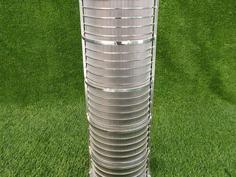
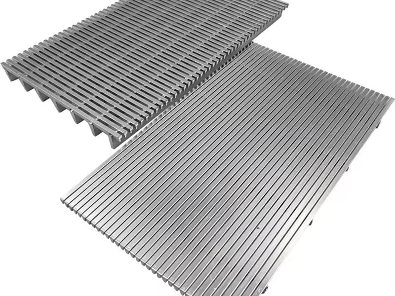
Atunci când debitul necesar al puțului nu poate fi atins la o viteză de intrare acceptabilă cu fanta dictată de retenție, soluțiile standard sunt mărirea diametrului sitei, lungirea sitei sau reducerea lățimii superioare a sârmei pentru a mări suprafața deschisă — în niciun caz mărirea fantei peste ceea ce poate tolera în siguranță formațiunea. De aceea tuburi de sită din sârmă profilată și cilindri de deshidratare și filtrare sunt disponibili într-o gamă largă de diametre, lungimi și profile de sârmă.
Comportament anti-colmatare și de autocurățare
Profilul în formă de V al sârmei este cel care face ca o sită wedge wire să fie rezistentă la colmatare. Fanta este cea mai îngustă la suprafața exterioară și se lărgește continuu spre interior. O particulă care este suficient de mică pentru a pătrunde în fantă are întotdeauna un spațiu de trecere din ce în ce mai mare înaintea sa, astfel încât să nu se poată bloca pe parcurs; o particulă care este prea mare nu intră deloc — aceasta rămâne pe suprafață, unde este antrenată de flux. Nu există niciun buzunar fără ieșire și nicio zonă de filtrare în adâncime în care particulele fine să se poată acumula și să colmateze permanent sita.
Comparați acest lucru cu plasa țesută: ochiurile pătrate de dimensiune fixă pot capta particule care sunt mai mici decât ochiul, dar mai mari decât spațiul liber pe diagonală, înțepenindu-le în interiorul țesăturii. În timp, acele particule se compactează, iar plasa se colmatează. Sitele wedge wire se bazează în schimb pe filtrare de suprafață: turta care se formează este afânată, sortată și se curăță la fiecare fluctuație de debit. În puțuri, acest lucru se traduce direct prin întreținere redusă, o dezvoltare mai ușoară și o durată de viață mai lungă, motiv pentru care această geometrie este specificată aproape universal pentru controlul nisipului și ciuruirea în minerit și agregate unde mediile colmatante ar opri altfel producția.
Calcule de cădere de presiune și debit
Pentru puțurile de apă și sistemele de desecare, criteriul hidraulic determinant este viteza de intrare — viteza medie a apei care trece prin deschiderile sitei. Practica din industrie menține viteza de intrare la sau sub 0.03 m/s (3 cm/s); peste acest nivel, particulele fine migrează, incrustarea se accelerează, iar sita se colmatează prematur.
Relația de bază este pur și simplu:
Q = v × A_open
unde Q este debitul (m³/s), v este viteza de intrare (m/s), iar A_open este aria deschisă a sitei instalate (m²).
Exemplu practic: un puț de deshidratare trebuie să asigure 20 m³/h (0.00556 m³/s). La o viteză maximă de intrare de 0.03 m/s, suprafața liberă necesară este:
A_open = 0.00556 / 0.03 ≈ 0.185 m²
Suprafața liberă a unei site cilindrice este A_open = suprafață liberă (%) × π × D × L. Cu o fantă de 0.5 mm la o suprafață liberă de 20% și un diametru exterior de 200 mm (0.2 m), fiecare metru de sită oferă aproximativ 0.126 m² de suprafață deschisă, astfel încât proiectul necesită aproximativ 1.5 m de sită cu fante. Dacă același puț ar folosi o fantă de 0.25 mm la o suprafață deschisă de 11.1%, ar avea nevoie de aproximativ 2.7 m — o ilustrare concretă a modului în care dimensiunea fantei, lungimea sitei și debitul sunt strâns legate.
Odată ce sita este dimensionată, căderea de presiune pe aceasta este mică — de obicei de la zeci până la câteva sute de milimetri de coloană de apă pentru apă curată — și este guvernată de suprafața deschisă și de viteza de apropiere. În puțurile împachetate și cele cu filtru de pietriș, pierderea de sarcină dominantă are loc în formațiunea propriu-zisă (curgere Darcy), nu în sită, cu condiția ca suprafața deschisă a sitei să nu fie restricția limitativă. Aceeași metodă de calcul se aplică la dimensionarea panourilor de sită wedge wire pentru paturi de filtrare și site, unde viteza de intrare țintă este ajustată pentru condițiile de proces.
Selecția materialului: SS304, SS316/316L și Duplex 2205
Dimensiunea fantei controlează hidraulica; materialul controlează durabilitatea. Chimia apei — conținutul de cloruri, pH-ul, hidrogenul sulfurat, oxigenul și încărcarea abrazivă — ar trebui să decidă marca de material înainte ca dimensiunea fantei să fie fixată.
Tabelul 3 — Compararea materialelor pentru sitele din sârmă profilată
| Proprietate | SS304 | SS316 / SS316L | Duplex 2205 |
|---|
| Compoziție tipică | 18% Cr; 8% Ni | 16–18% Cr; 10–14% Ni; 2–3% Mo | 22% Cr; 5% Ni; 3% Mo; N |
| Rezistență la coroziune | Bună în apă dulce; substanțe chimice ușoare | Excelentă în cloruri și aplicații corozive generale | Superioară în medii cu conținut ridicat de cloruri; H₂S; și medii acide |
| Rezistență la pitting / coroziune în spații înguste | Moderată | Bună (Mo o îmbunătățește) | Cea mai mare dintre cele trei (PREN ≥ 35) |
| Rezistență mecanică | Standard | Standard | ~2× limita de curgere a 304 |
| Utilizări tipice | Filtrare generală; alimentară; puțuri de apă dulce | Puțuri municipale și industriale; apă de mare; ape uzate | Offshore; saramură; fluide miniere și de puț agresive |
| Cost relativ | Cel mai mic | Moderat | Cel mai mare |
Pentru un puț domestic de apă dulce, SS304 este complet adecvat. Pentru puțuri municipale, industriale sau de coastă cu niveluri ridicate de cloruri, SS316/316L este alegerea implicită deoarece molibdenul rezistă la pitting și la coroziunea în spații înguste la marginile fantelor — partea cea mai sensibilă la coroziune a sitei. Acolo unde nivelurile de cloruri sunt extreme, este prezent hidrogenul sulfurat sau abraziunea este severă (șlam minier, saramură, ape termale), duplex 2205 combină o limită de curgere de aproximativ două ori mai mare decât cea a 304 cu o rezistență net superioară la fisurarea prin coroziune sub tensiune indusă de cloruri, permițând profile de sârmă mai fine și deschideri fără suport mai lungi. KAIFIL sudează complet fiecare intersecție, astfel încât materialul de bază — nu îmbinarea — guvernează performanța la coroziune.
Cum să alegeți dimensiunea corectă a fantei: Pas cu pas
- Definiți cerințele de lucru. Notați ce trebuie să rețină sita (tipul de formațiune, dimensiunea țintă a particulelor sau specificația de proces) și debitul necesar, în m³/h sau L/min.
- Efectuați o analiză granulometrică prin cernere. Dacă nu există o curbă granulometrică, cerneți o probă reprezentativă și trasați curba PSD. Extrageți D10, D30, D50, D60 și Cu = D60/D10.
- Selectați dimensiunea fantei în funcție de formațiune. Utilizați regulile bazate pe Cu de mai sus sau Tabelul 1 ca punct de plecare: nisip fin → 0,2–0,3 mm, nisip mediu → 0,3–0,5 mm, nisip grosier → 0,5–1,0 mm, pietriș → 1,0–3,0 mm.
- Verificați suprafața deschisă și capacitatea de debit. Calculați suprafața deschisă pentru fanta și profilul sârmei selectate, apoi verificați dacă ecuația Q = v × A_open este respectată la v ≤ 0.03 m/s. Ajustați diametrul, lungimea sau profilul sârmei — nu fanta — dacă debitul este insuficient.
- Verificați comportamentul la colmatare. Confirmați că cele mai mici particule care trebuie să treacă sunt considerabil mai mici decât fanta, astfel încât nicio fracțiune de dimensiune apropiată să nu se poată bloca în fanta în V.
- Selectați materialul. Adaptați marca de material la chimia apei și la abraziune: SS304 pentru apă dulce, SS316/316L pentru cloruri și aplicații industriale generale, duplex 2205 pentru medii agresive sau abrazive.
- Specificați geometria completă. Alegeți forma sitei — țeavă, cilindru, panou sau piese personalizate de sită din sârmă profilată în V — plus diametrul exterior, lungimea, direcția fantei, conexiunile de capăt și toleranțele. Confirmați toleranța fantei (de obicei ±0,05 mm) cu producătorul.
- Validați. Dacă aplicația este critică, efectuați un test pilot sau de referință cu mediul de filtrare real și ajustați fanta înainte de producția completă.
Întrebări frecvente
Care este cea mai mică dimensiune a fantei disponibilă? Sitele standard din sârmă profilată KAIFIL încep de la 0.1 mm. Deschiderile sub 0.1 mm sunt posibile, dar reduc aria deschisă și cresc căderea de presiune, fiind rareori necesare deoarece formarea de punți permite unei fante de 0.1–0.2 mm să controleze eficient sedimentele foarte fine.
Ce dimensiune a fantei ar trebui să folosesc pentru nisip fin? Pentru nisip fin (granule de aproximativ 0.15–0.25 mm), recomandarea standard este o fantă de 0.2–0.3 mm. Confirmați pe baza analizei granulometrice: fanta ar trebui să se încadreze în intervalul D30–D50 pentru formațiuni uniforme.
Cum afectează dimensiunea fantei debitul? Capacitatea de curgere este proporțională cu suprafața deschisă, care crește odată cu lățimea fantei. Lărgirea unei fante de la 0.25 mm la 0.5 mm (pe aceeași sârmă) dublează aproximativ suprafața deschisă și debitul la aceeași cădere de presiune — dar o fantă mai lată permite, de asemenea, trecerea unei cantități mai mari de material de formațiune, de aceea retenția trebuie verificată întotdeauna mai întâi.
Care este diferența dintre dimensiunea fantei și dimensiunea ochiului? Dimensiunea fantei este lățimea spațiului continuu în formă de V dintr-o sită cu sârmă profilată (wedge wire). Dimensiunea ochiului reprezintă numărul de deschideri pe inch dintr-o țesătură metalică, care are ochiuri pătrate, de dimensiune fixă. O fantă wedge wire oferă o filtrare continuă de suprafață și rezistă la colmatare, în timp ce plasa filtrează în profunzime și se poate colmata. Consultați detaliile din comparația dintre wedge wire și plasa țesută.
Cum măsor lățimea fantei? Lățimea fantei este verificată cu lere de grosime sau lamele de calibrare introduse în fantă, sau cu un comparator optic pentru dimensiuni mai fine. La sitele KAIFIL, fanta este stabilită de pasul de înfășurare al sârmei profilate în timpul fabricării și este menținută la o toleranță tipică de ±0.05 mm; o simplă verificare de tip trece/nu trece cu lera în câteva puncte de pe circumferință confirmă deschiderea înainte de instalare.
Obțineți o ofertă de preț pentru sită cu sârmă profilată în V personalizată
Alegerea dimensiunii corecte a fantei face diferența între o sită care oferă un debit curat și ridicat timp de decenii și una care pompează nisip sau se colmatează în câteva luni. KAIFIL elaborează recomandări pentru fantă, profilul sârmei și material pe baza analizei granulometrice, a chimiei apei și a debitului țintă — gratuit și fără nicio obligație.
Pentru a solicita o ofertă de preț, trimiteți-ne dimensiunea fantei (sau analiza dimensiunii granulelor), diametrul și lungimea sitei, clasa materialului și aplicația. Furnizăm tuburi de sită cu sârmă profilată în V, cilindri, panouri și, complet personalizate, componente de filtrare din oțel inoxidabil realizate conform desenului dumneavoastră. Contactați departamentul de vânzări KAIFIL astăzi și vă vom confirma deschiderea corectă a fantei pentru puțul, sistemul de desecare sau procesul dumneavoastră de filtrare — și o vom livra cu certificare completă a materialului.