A water distributor is a hydraulic device—typically a header pipe fitted with lateral screens, or a single slotted screen assembly—that spreads incoming feedwater uniformly across the cross-section of an ion exchange, mixed-bed, or degasification vessel. In a demineralized (DI/deionized) water treatment plant, stainless steel distributors are engineered around three numbers: slot widths of 0.25–1.0 mm, open areas of 30–60%, and distribution velocities that keep lateral pipe velocity below roughly 0.6 m/s while slot velocity stays in the 0.3–1.5 m/s range. A properly sized distributor also follows two geometric rules: the total open area of the distribution openings should be 1.5–3 times the cross-sectional area of the header pipe, and the freeboard above the bed must accommodate 50–100% backwash expansion in mixed-bed service. Getting these parameters right determines whether every resin bead is contacted equally—and whether the unit delivers consistent effluent quality to the end of its service cycle.
Why Distributor Design Matters in Demineralized Water Service
Demineralized water systems are different from raw-water filtration in one critical way: the vessel must convert ionic load uniformly, or the bed exhausts unevenly. When flow concentrates in one zone of a mixed-bed polisher, the local resin exhausts first, sodium or silica leaks through that channel, and the whole train has to be regenerated early. The distributor is the only component that controls where that water goes.
Resin Retention: Slot Must Be Smaller Than the Resin Bead
Ion exchange resins are granular, typically 0.4–1.2 mm in diameter for mixed-bed polishing (0.3–1.2 mm for standard cation and anion grades). If the distributor opening is larger than the smallest bead, resin migrates into the header, contaminates downstream polishing stages, and renders the unit ineffective. The first design rule is therefore simple: the slot width must be smaller than the resin particle. For most DI service this means 0.2–0.5 mm slots, and for mixed-bed polishers carrying fine mesh resins, 0.2–0.25 mm is common. Our resin trap wedge wire filter selection guide walks through how slot width is matched to media size—the same principle that protects your distributor.
Even Bed Loading and Low Pressure Drop
Uniform distribution protects the bed and keeps plant operating cost low. Uneven flow creates channeling, which wastes regenerant, shortens run length, and degrades water quality. At the same time, the distributor must not be a throttling device: a well-designed distribution system adds only 0.15–0.5 bar (2–7 psi) to the overall vessel pressure drop at design flow. Any more, and pumping energy and service pressure are wasted.
Distributor Configurations: Lateral and Header Systems
The two dominant geometries in DI plants are the header-lateral system and single-point radial distribution. Both are built around the same hydraulic idea: create enough resistance at the openings so that every opening delivers nearly identical flow regardless of position along the header.
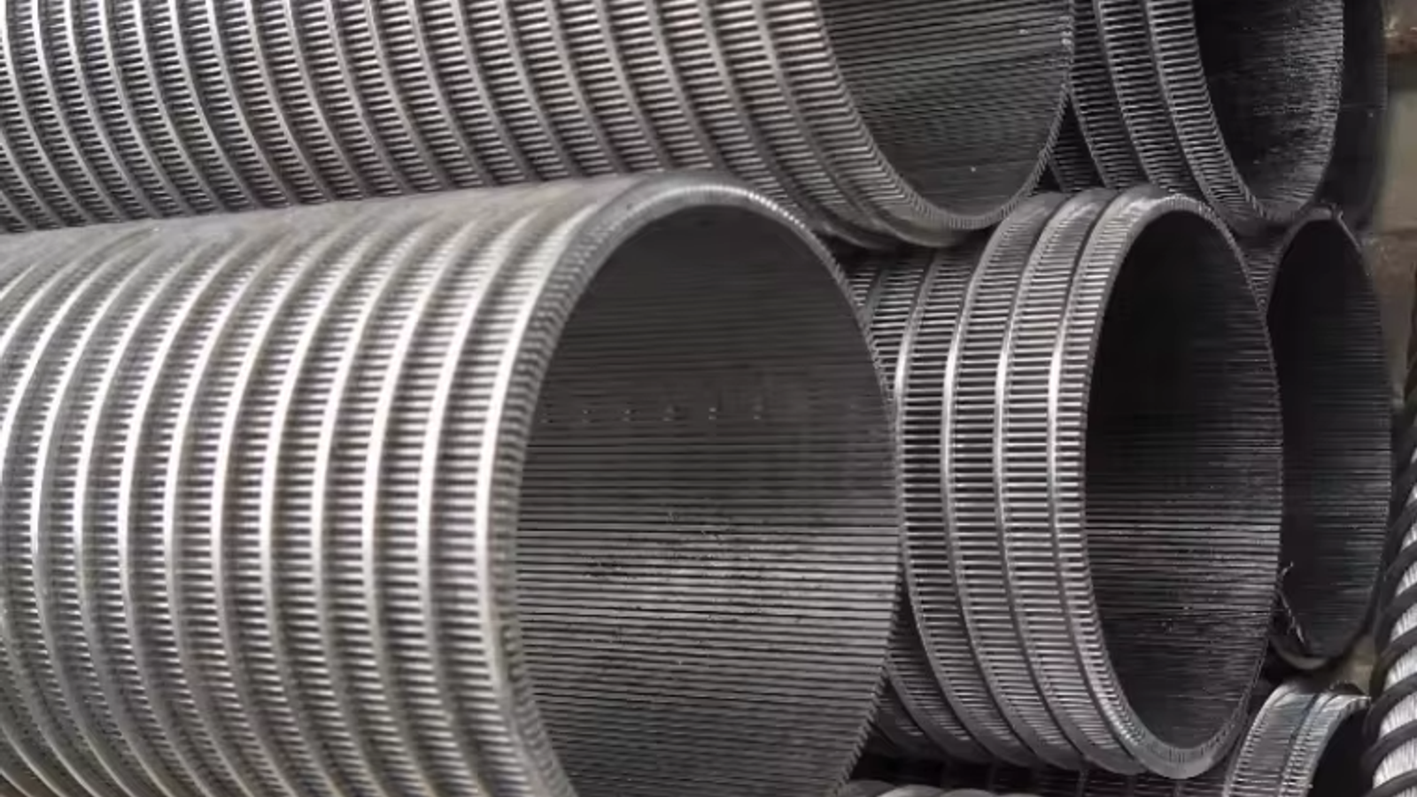
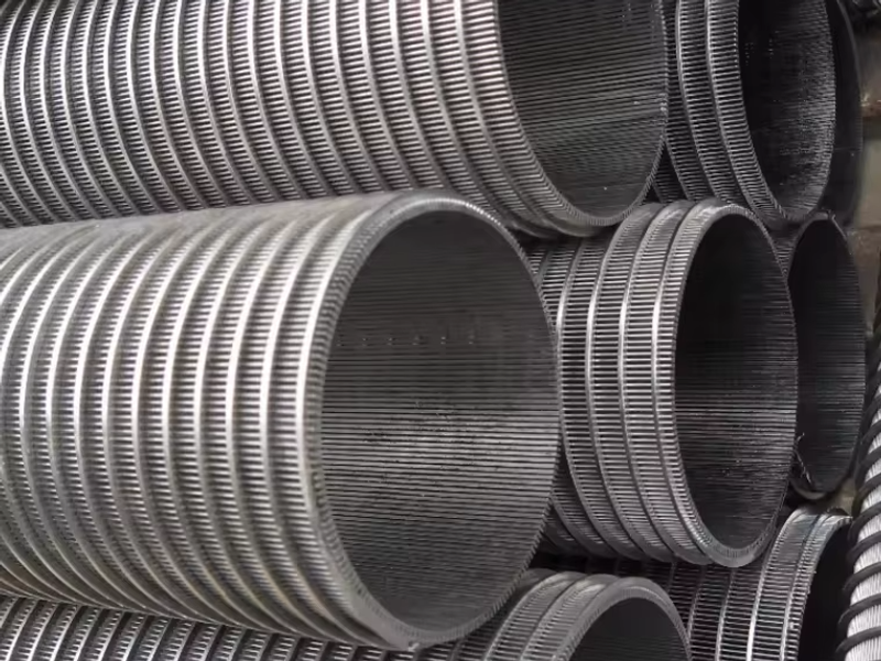
In a header-lateral system, a central header pipe runs vertically or horizontally, and a set of lateral screens branches off it. Each lateral is a slotted screen—typically a wedge wire screen pipe or a perforated tube—positioned to distribute flow across the bed. Laterals are spaced so that their influence zones overlap evenly, usually 150–300 mm apart in smaller vessels and scaled up with vessel diameter. The header is sized so that velocity stays low, preventing the first lateral from stealing flow from the last.
Deck-Mounted Laterals for Polishing Units
For mixed-bed and polishing vessels, laterals are often mounted through a false floor (support deck), with a screen or tube section above the deck and a connection below. This configuration keeps the distributor rigid, prevents bed movement from shifting the screens, and allows each lateral to be inspected and replaced without dumping the vessel. Because mixed beds are backwashed at 8–12 m/h to separate cation and anion resin, deck-mounted wedge wire screen cylinders see severe mechanical and hydraulic load—continuous-slot construction survives this cycling far better than drilled tubes alone.
Degasser Distribution
In decarbonator and degasser service, water is distributed over the top of random or structured packing. Here the distributor's job is to wet the packing uniformly with a thin film, so open area and drip-point spacing matter more than fine slot tolerance. Perforated trays and slotted laterals are both common; the same stainless steel distributor design rules apply, but slot widths can be coarser because there is no resin to retain.
Choosing the Element: Wedge Wire vs. Perforated Tube vs. Mesh-Wrapped
Three screen formats dominate distributor construction. They differ in strength, clogging resistance, open area, and cost—and the right choice depends on service.
| Feature | Wedge Wire (V-profile) | Perforated Tube | Mesh-Wrapped Tube |
|---|
| Mechanical strength | High (rigid continuous rods) | High (drilled tube wall) | Moderate (wire cloth on support) |
| Clogging resistance | Excellent (tapered slot self-cleans; non-plugging) | Moderate (straight holes blind if debris bridges) | Low (mesh strands trap fibers) |
| Open area | 30–60% | 20–40% | 30–50% |
| Slot tolerance / precision | Precise; continuous slot 0.1 mm increments | Limited by hole pattern and ligament strength | Dependent on mesh weave; less precise |
| Resin retention reliability | Very high | Good if holes < resin | Good; but media can lodge in mesh |
| Relative cost | Higher | Lower | Medium |
When Wedge Wire Beats Perforated Pipe
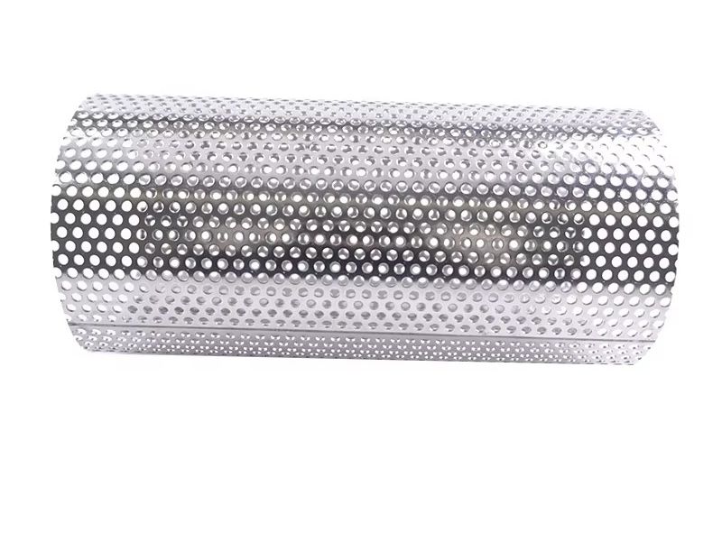
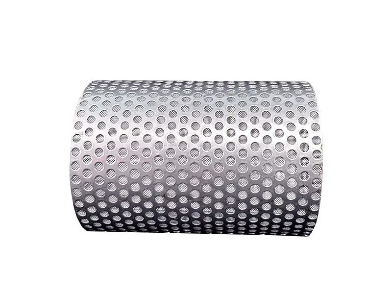
Perforated pipe is the budget workhorse, and it is adequate where the distributor is clean, the media is coarse, and flow is steady. But in demineralized water service three factors push engineers toward wedge wire. First, the V-shaped continuous slot is self-cleaning: the gap widens inward, so particles that enter are ejected rather than wedged in the hole—critical when resin fines and regeneration debris are present. Second, wedge wire reaches open areas of 50–60%, while a perforated tube is limited to roughly 40% before the ligament between holes loses strength. Higher open area means lower slot velocity and lower pressure drop at the same flow. Third, continuous-slot construction is structurally rigid, which matters on long laterals and under backwash. For high-purity polishing duty where a single failed hole can release resin into the product, the reliability margin is worth the premium. If your design is cost-sensitive, stainless steel perforated filter tubes and perforated metal filter cylinders remain a sound choice for coarse-distribution and pre-filter stages.
Sizing Rules and Slot Selection
Slot Sizing vs. Resin Bead Size
The governing rule: slot width < smallest resin bead. Standard cation and anion resin grades run 0.3–1.2 mm; mixed-bed polishing grades typically run 0.4–1.0 mm. In practice, distributor slots for DI service are selected at 0.25–0.5 mm for standard grades and 0.2–0.25 mm for mixed-bed polishers, giving a safety margin against fines and broken beads. When resin grade is not fixed, specify the slot against the finest resin the plant may ever load. Our wedge wire screen slot size selection guide provides a full slot-to-media matching table.
Open Area Targets
Open area is the ratio of open opening to total screen surface, and it drives both pressure drop and flow uniformity. Targets by element type:
- Wedge wire laterals: 40–60% open area.
- Perforated laterals: 25–40% open area.
- Total distributor open area vs. header: 1.5–3 times the header cross-sectional area.
Distribution Velocity and Flow Rate per Lateral
Keep lateral pipe velocity below 0.3–0.6 m/s (1–2 ft/s) so the static pressure change along the lateral stays small relative to the drop across the openings. Slot velocity—the velocity through the openings themselves—should sit in the 0.3–1.5 m/s range at design flow; going much higher erodes screens and inflates ΔP, going much lower can allow uneven draw. From these limits, flow rate per lateral follows: for a typical 25 mm (1") lateral at 0.5 m/s, that is roughly 1.5–2.5 m³/h per lateral; a 50 mm (2") lateral carries roughly 7–10 m³/h. The number of laterals is then set by dividing total service flow by per-lateral capacity, rounding up, and checking spacing against bed area.
Pressure Drop Budgeting
Budget the distributor's clean ΔP at 0.15–0.5 bar at design flow. Two sub-rules keep distribution uniform: the pressure drop through the openings should be at least 5–10 times the velocity head in the lateral pipe, and the distributor ΔP should remain below about 25–30% of the total vessel head loss at end of run so that fouling, not the distributor, governs exhaustion. Include a fouling allowance of 20–30% so the system still distributes evenly as openings age.
Backwash Flow Considerations
The distributor must also pass backwash without channeling. Typical backwash rates are 10–15 m/h for strong-acid cation, 5–10 m/h for strong-base anion, and 8–12 m/h for mixed beds during resin separation. Because backwash often exceeds service flux, confirm the screen open area and slot velocity at backwash flow, not just at service flow. Backwash water and air scour also impose the highest mechanical loads—another reason continuous-slot, rigid wedge wire construction is favored on laterals that must survive decades of cycling.
Uniformity is achieved by design, not inspection. The two most important controls are the open-area ratio and vessel freeboard.
Ratio of Distributor Open Area to Pipe Cross-Section
The classic rule for lateral distribution systems is that the total area of all openings must be substantially larger than the cross-sectional area of the header—commonly 1.5–3 times. This forces the pressure drop to occur at the openings rather than along the header, so a pressure change in the pipe does not translate into a large flow change at the openings. At ratios near 1:1, the laterals near the inlet pass more flow and the far laterals starve; at 2:1 and above, flow is effectively uniform. For high-flow mixed-bed polishers, engineers often target the 2.5–3:1 end of the range.
Freeboard and Headroom Rules
Freeboard is the empty height above the resin bed that allows the bed to expand during backwash. Standard guidance: provide 50–80% freeboard for mixed-bed units (where resin separates during backwash) and 25–50% for single-bed cation or anion units. For the distributor itself, keep at least 150–300 mm between the top of the bed and the underside of the upper distributor, and ensure the inlet diffuser breaks the jet before it reaches the screen—otherwise high-velocity inlet water erodes a crater in the resin and creates a permanent channel. In degassers, maintain a similar quiet zone above the packing so the distributor film forms evenly.
Materials: SS304 vs. SS316L for Demineralized Service
Both SS304 and SS316L are used in demineralized water plants, but the choice matters. Demineralized water has very low conductivity, which can make stainless steel more susceptible to localized corrosion under the right conditions, and any chloride breakthrough will attack 304 aggressively. Standard practice:
- SS304 for general cation and anion service where chloride content is low and water is warmer or treated consistently.
- SS316L for mixed-bed polishers, final polishing, and any plant with variable feed, chlorinated makeup, or seawater influence. Molybdenum gives 316L markedly better pitting and crevice resistance.
- Both must be pickled and passivated after welding; poor weld heat-tinting is the most common cause of premature distributor failure in DI plants.
When you need a fully welded assembly—laterals, header, flanges, and support spiders—specify a fabricator that supplies complete custom wedge wire screen parts, not just raw screen, so weld quality and passivation are handled as one.
Design Checklist for a Stainless Steel Water Distributor
Use this checklist to lock down a specification before sending it for quotation:
- Service data: service and backwash flow rates (m³/h or m/h), operating pressure, temperature.
- Vessel geometry: inside diameter, straight-side height, bed depth, inlet/outlet nozzle locations.
- Resin data: resin type and grade, bead size range (confirm slots < smallest bead).
- Number of laterals: sized so lateral pipe velocity ≤ 0.6 m/s, spaced evenly across the bed.
- Slot width: 0.2–0.5 mm depending on resin; continuous slot for wedge wire.
- Open area: 40–60% for wedge wire; total open area 1.5–3× header cross-section.
- Flow uniformity: distributor ΔP 0.15–0.5 bar at design flow; opening ΔP ≥ 5–10× lateral velocity head.
- Backwash: confirm slot velocity and structural load at backwash and air-scour rates.
- Materials: SS304 for standard service, SS316L for mixed-bed/polishing and chloride risk; pickled and passivated welds.
- Freeboard: 50–80% (mixed bed) or 25–50% (single bed) for backwash expansion.
FAQ
What slot width should I specify for a demineralizer distributor? Match the slot to the finest resin in the vessel. For standard cation/anion resin (0.3–1.2 mm beads) use 0.25–0.5 mm slots; for mixed-bed polishing resin (0.4–1.0 mm) use 0.2–0.25 mm. The slot must always be smaller than the smallest resin bead.
Why is wedge wire preferred over perforated pipe for DI distributors? Wedge wire provides higher open area (40–60% vs. ~40% max for perforated), a self-cleaning tapered slot that resists blinding by resin fines, and rigid continuous-slot construction that survives backwash cycling. It costs more, but it is the reliability standard for mixed-bed polishers where a failed opening means resin in the product.
How many laterals do I need? Size each lateral so pipe velocity stays below 0.6 m/s, then divide total service flow by per-lateral capacity. As a starting point, a 25 mm lateral carries roughly 1.5–2.5 m³/h and a 50 mm lateral roughly 7–10 m³/h. Verify spacing gives even coverage across the bed.
What open area is required for even distribution? Perforation or slot open area of 40–60% for wedge wire, and a total distributor open area of 1.5–3 times the header cross-sectional area. This ratio is the single most important control for flow uniformity in header-lateral systems.
Should I use SS304 or SS316L? SS304 is adequate for standard cation/anion service with low chloride feed. Use SS316L for mixed-bed polishers, final polishing, and plants with chloride breakthrough risk or seawater influence—the molybdenum content provides the pitting resistance demineralized and borderline feedwaters demand.
Get a Free Distributor Design Review
Every demineralized water train deserves a distributor that delivers uniform flow for the life of the vessel. Send us your vessel diameter, bed height, resin type and bead size, and service and backwash flow rates, and our engineers will return a complete distributor design review: lateral count and spacing, slot width, open area, and a pressure-drop calculation—at no cost. Vessel drawings (DWG, DXF, or PDF) are welcome, and we typically reply with a quick quotation within 24 hours. Contact the KAIFIL engineering team to start your review today.