Technical
Stainless Steel Filter Tube Support Core: Open Area & Design
Learn how a stainless steel filter tube support core sets open area, flow and collapse strength. Get a quote on custom filter tubes from KAIFIL.
Learn how a stainless steel filter tube support core sets open area, flow and collapse strength. Get a quote on custom filter tubes from KAIFIL.
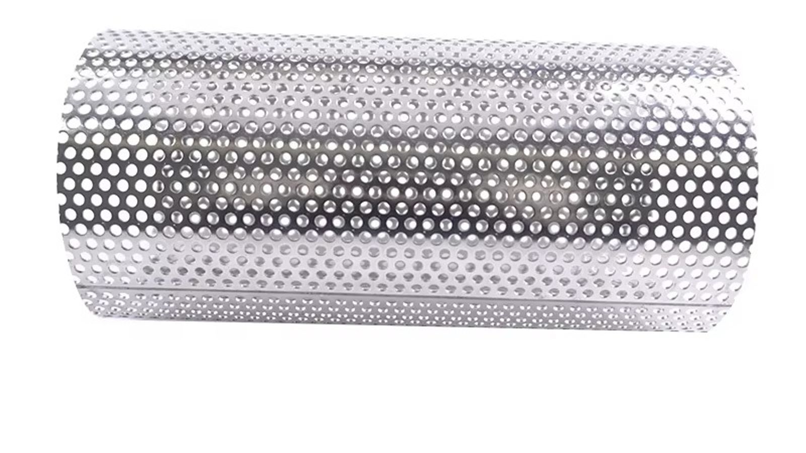
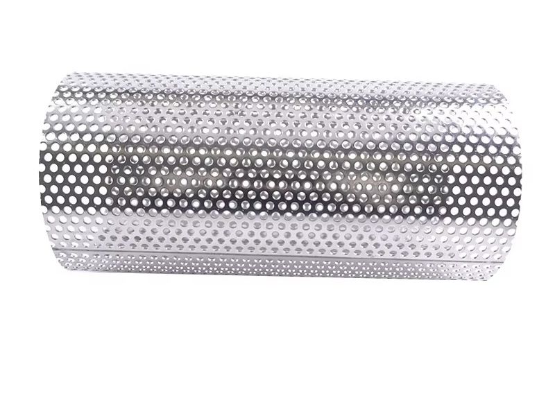
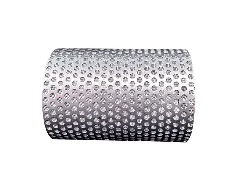
A stainless steel filter tube support core is the perforated metal skeleton that sits directly beneath the woven or sintered wire mesh of a layered filter tube, combining mechanical backing, drainage, and collapse resistance in a single structure. In a typical two-layer assembly, a 0.1–0.3 mm thick woven 316L mesh (20–500 mesh, roughly 30–750 µm nominal openings) is welded or sintered over a perforated metal cylinder whose wall is usually 1.0–3.0 mm thick, with round holes between 1.0 and 6.0 mm in diameter on a staggered or straight pitch. The open area ratio of that core — normally 15–40% of the cylindrical surface — is the single most influential parameter in the assembly. Get it too low and the core chokes the filter; get the hole pattern wrong and the mesh sags, dimples, and tears; get the wall too thin and the whole stainless steel perforated filter tube collapses inward the first time differential pressure spikes. This article explains how to design and specify the support core so the media, not the skeleton, controls filtration performance.
Buyers often spec a filter tube by its mesh micron rating and assume the underlying core is a passive component. It is not. The support layer performs three load-bearing functions that directly determine filtration efficiency, flow capacity, collapse strength, and service life.
Media support. Woven wire mesh is a flexible textile-like structure. Between support points it will deflect, and once the unsupported span exceeds roughly 30 wire diameters, the weave begins to cone into the hole, opening the pores locally. That turns a calibrated 50 µm surface into a sieve with scattered 200 µm leaks — fines pass exactly where the engineer assumed none could. The core's hole pattern sets the maximum unsupported span and therefore the integrity of the mesh's pore structure under load.
Drainage and filtrate path. After a particle is captured on the mesh surface, the filtrate must leave the media quickly. If the core restricts the flow path, backpressure builds beneath the cake and drives premature blinding or fines migration. The core is the first drainage layer in the filter, and its open area relative to the media's open area dictates where the pressure drop is actually located.
Structural strength. The mesh provides almost no hoop or axial strength. All collapse and burst resistance comes from the core cylinder, plus whatever end caps, ferrules, or seams are welded to it. Under backwash, a reverse differential of several bar is common, and a thin or weakly perforated core will buckle before the mesh does.
A support core that fails any of these three jobs produces the same visible symptom — a filter that behaves far below its rated performance — which is why the open area ratio and hole geometry deserve as much engineering attention as the micron rating itself.
Open area ratio is the percentage of the core's surface that is actually open hole, and it is a direct trade-off between flow and strength. Higher open area means more drainage and lower clean pressure drop; lower open area means more remaining metal to carry hoop stress and more land for welding and stiffness.
For round holes on a straight or staggered pattern, the achievable open area on a cylinder tops out around 40% before the remaining ligaments between holes become too thin to be practical. Below roughly 15%, the core begins to act like a throttling orifice for most woven media. The practical design band for stainless steel filter tube support cores is therefore 15–40%, with most production cores sitting at 25–35%.
| Open area ratio | Typical ΔP contribution | Collapse strength | Best fit |
|---|---|---|---|
| 15–20% | High (core becomes flow-limiting; ≥25% of total ΔP) | Highest (more solid metal; thicker ligaments) | High-pressure gas; reverse-pulse backwash; deep wells |
| 25–30% | Moderate (≤10–15% of total ΔP) | High | Standard liquid filtration; most industrial processes |
| 30–35% | Low (core rarely limits flow) | Moderate | High-flow filtration; pleated cartridges |
| 35–40% | Negligible (core is effectively invisible to flow) | Reduced (thin ligament webs; limits) | Clean fluids; low ΔP service; drainage-only screens |
A useful design rule is that the core open area should be at least 1.5–2× the media open area so the mesh — not the skeleton — governs the filter's behavior. A 100-mesh weave has roughly 30–35% open area, so a 30–40% core is appropriate; a 20-mesh coarse screen can be comfortably backed by a 25% core. Conversely, using a low-open-area core under a high-open-area mesh starves the media: the mesh may be rated for 5 m³/h at a given ΔP, but the core silently cuts the effective capacity, and the apparent "dirty filter" behavior is actually a core bottleneck.
The open area also controls clean pressure drop. A clean layered filter tube typically shows 0.1–0.5 bar ΔP at design flow; if the core's open area drops below ~20%, its own ΔP can consume a quarter or more of that budget, leaving less headroom before the change-out or cleaning threshold.
Open area tells you how much flow can pass, but hole size and pitch tell you whether the mesh will be supported without sagging. Two cores with identical 30% open area can behave completely differently — one with 1.5 mm holes on a tight pitch supports a fine weave cleanly, while another with 6 mm holes on a wide pitch lets the same mesh balloon between supports.
For woven mesh support, follow these practical rules:
Staggered (60°) hole patterns give better support than straight patterns at the same open area, because the supporting lands between holes offset in both axes. The minimum land (the metal bridge between adjacent holes) should not fall below roughly 1× the hole diameter for strength, and the hole edge must be deburred or roll-burnished on the media side — a sharp burr is a wear point that saws through the mesh under vibration and flow.
One more rule that prevents field failures: the core's pore size should be larger than the media's pore size (otherwise the core partially filters and blinds), but the largest hole in the core must still be small enough that the media can't be extruded into it at maximum operating ΔP. For fine sintered elements, this is why manufacturers build sintered metal filter elements as fully fused media-and-support composites rather than two separate layers.
The third variable set is geometry. The core cylinder's outside diameter, wall thickness, length, seam, and end weld all set the collapse rating and the practical limit for service life under cycling.
Wall thickness and collapse strength. For a 60 mm OD cylinder, a 1.5 mm wall with a 30% staggered hole pattern typically withstands several bar of differential; doubling the wall to 3 mm roughly doubles the available collapse margin and extends the backwash cycle count before fatigue cracks appear. If the process has reverse-flow backwash at 5–10 bar, the core wall and hole pattern must be designed for that number, not the forward-flow operating ΔP. In oil and gas and petrochemical duty, where pressure excursions are routine, this collapse margin is the difference between a 5-year element and a 5-week one — see how these assemblies are applied in oil & gas petrochemical service.
Seam design. Seamless drawn cores are strongest but limited in diameter and hole pattern. Most custom cores are rolled from a perforated sheet and joined by one of three methods:
| Support structure | Open area | Strength | Drainage | Typical use |
|---|---|---|---|---|
| Perforated metal core (rolled; seam-welded) | 15–40%; precisely controlled | High; predictable | Excellent; uniform | Most layered filter tubes and cylinders |
| Expanded metal support | 30–60%; but irregular diamond openings | Moderate | Good; but diamond openings create uneven mesh support | Light-duty; cost-sensitive screens |
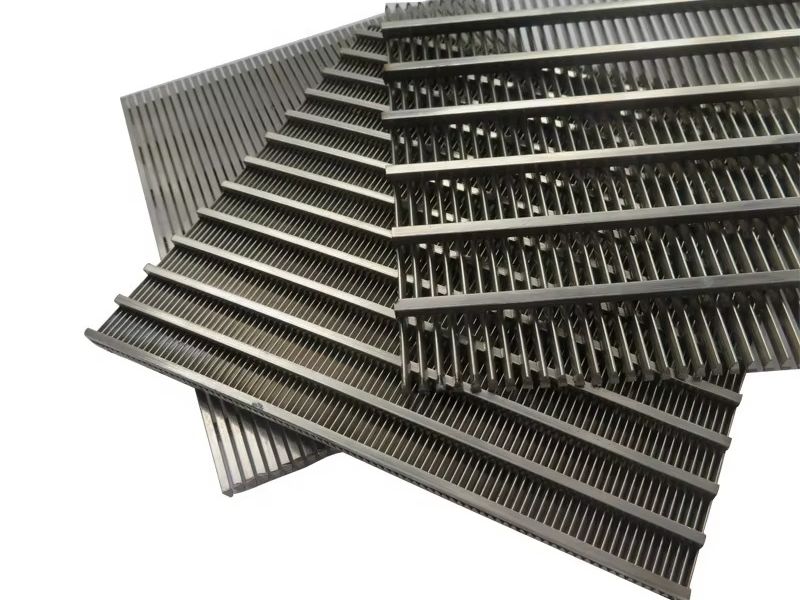
| Wire-wound / helically wound support | 50–70% | Moderate | Excellent | Pleated and heavy-duty cartridge inner cores |
A longitudinal butt seam, TIG-welded through the wall, preserves open area and strength best but must be ground flush on the media side — a proud weld bead creates a high spot that wears the mesh and leaks at the interface. Overlapping (lap) seams are easier to build but add a double-thickness step. For lengths beyond standard sheet width, spiral lock-seams or multiple butt welds are common; each weld is a potential crack initiation point under thermal and pressure cycling, so the weld schedule should match the material. 316L cores weld cleanly and hold their corrosion resistance, but the heat-affected zone still needs pickling or passivation after welding to avoid localized attack in chloride service.
Pleat geometry. When the assembly is a pleated filter cartridge, the core becomes the inner cage that defines the pleat depth and prevents pleat collapse. Pleat count is limited by the inner core's circumference and the minimum pleat radius that won't pinch the media against the core holes; too many pleats and the outer pleats starve, too few and surface area is wasted. The core must also provide the axial drainage channels that carry filtrate out through the end cap.
End closures. Where the mesh meets the end caps, the joint must be a full-penetration weld or a mechanically sealed ferrule, because this interface is the most common leak path. Tri-clamp and threaded ferrules are standard on sanitary designs and are covered in KAIFIL's welded wire mesh filter assemblies line for custom end-treatments.
When ordering a custom layered filter tube or perforated metal filter cylinder, a complete spec sheet prevents the costly "we thought you meant the other thing" round-trip. Provide, at minimum:
For temperature and material questions, a good starting point is the guide on high-temperature stainless steel filter tube materials — but for the core itself the same material logic applies to the perforated sheet, which must match or out-spec the mesh in wall thickness and corrosion allowance.
Failure mode one is starvation. A core with too little open area forces high velocity through its holes; the mesh above each hole erodes in a circular pattern, and the filter builds pressure drop until it is replaced on a fraction of its rated cycle. Failure mode two is collapse: a thin core with wide holes buckles inward on the first backwash pulse, crushing the mesh into the gap and permanently opening pores. Failure mode three is fatigue at the weld and hole ligaments under thermal and pressure cycling, which shows up as longitudinal cracks that let unfiltered process fluid bypass the media entirely. Each of these shortens service life dramatically and — worse — does it invisibly, because the filter still "works" while passing particles. Proper backwash design helps, but only if the core survives the pulse; the regeneration behavior of layered media is covered in depth in our guide on sintered mesh backwash regeneration.
What is a good open area ratio for a stainless steel filter tube support core? 15–40%, with 25–35% as the practical sweet spot for most liquid and gas filtration. Choose the upper end for high-flow duty and the lower end for high-pressure or aggressive-backwash service.
What size holes should the support core have? For standard woven mesh (80–200 mesh), 2–3 mm round holes on a staggered pitch. Use 1–2 mm for fine weaves, up to 4–6 mm for coarse screens, and a sintered composite for sub-50 µm media.
How does a poor support core affect filtration efficiency? It starves the mesh (reducing flow capacity), lets the weave cone into oversized holes (creating particle leaks well above the rated micron size), or collapses under differential pressure — all of which degrade efficiency regardless of the mesh rating.
Can the perforated core handle backwash differential pressure? Yes, if it is designed for it. Specify the maximum reverse ΔP on the data sheet and select wall thickness and hole pattern accordingly; a 2–3 mm wall with a staggered 30% pattern is a common starting point for 5–10 bar backwash.
How do I order a custom layered filter tube or cylinder? Send the spec sheet fields listed above — media, core, dimensions, end fittings, and operating envelope — to KAIFIL for engineering review and a quote.
Every filtration system is a compromise among open area, strength, and cost, and the right support core is the component that reconciles them. KAIFIL manufactures stainless steel filter tubes and cylinders in Shijiazhuang, China, with woven mesh, sintered media, and perforated cores fabricated in-house — including perforated metal sheet — so the support layer and the media are designed as one assembly, not two parts that happen to be welded together. Send us your process data and current drawing; our engineers will recommend the open area ratio, hole geometry, and wall thickness for your flow, ΔP, and temperature, and provide samples before you commit. Contact KAIFIL for a custom quote today.
Perforated tubes / cylinders / sleeves for filter cores, protective sleeves and liquid strainer supports, supplied to drawing with material, size and packing details confirmed at RFQ stage.
Cylinders / tubes / sleeves for filter support cores and protective sleeves, supplied to drawing with material, size and packing details confirmed at RFQ stage.
Perforated metal sheet for filter support, guards, screens and custom formed components.
Send drawings, dimensions, material, environment or operating conditions, and we will help confirm the right specification.
Uploaded reference files are included with the inquiry. For larger CAD packages, reply to the confirmation email or send them here:
Our team typically replies within 24 business hours.