Technical
Sintered Metal Filter Pressure Drop: How to Size Elements
Read sintered metal filter pressure-drop curves, learn the ΔP factors, and size filter elements from a pressure-drop budget. Contact KAIFIL for a free quote.
Read sintered metal filter pressure-drop curves, learn the ΔP factors, and size filter elements from a pressure-drop budget. Contact KAIFIL for a free quote.
Sintered metal filter pressure drop is the resistance to flow created by the filter element itself, expressed as the difference between upstream and downstream pressure (ΔP) at a given flow rate. In practical terms, it is the pumping energy you pay for every micron of filtration you buy: a clean sintered stainless steel element rated at 20 μm typically contributes 0.1–0.3 bar (10–30 kPa) of pressure drop at liquid fluxes of 20–40 m³/h per m², while a finer 0.5 μm sintered powder element can run three to five times higher. Because this resistance is predictable — it follows Darcy's law in the laminar flow range — the manufacturer's pressure drop vs flow rate curve is the single most useful tool for sizing and selecting a sintered metal filter element before a single drawing is issued.
Every serious sintered filter datasheet ships with a pressure drop vs flow rate curve, usually plotted as ΔP in bar or kPa on the vertical axis against volumetric flow in m³/h (either per element or per square metre of effective area) on the horizontal axis. Reading that curve correctly is the first step in any selection.
For a clean element the curve starts at the origin and rises almost linearly at low velocities. This linear segment is the Darcy region: flow is laminar inside the tortuous pore network, and ΔP is directly proportional to velocity. As flux increases, the relationship bends upward because inertial (Forchheimer) losses begin to dominate inside the pores. A well-designed sintered element operating inside its recommended envelope stays close to that linear region — that linearity is precisely what makes sizing arithmetic possible.
Three things to extract from the curve:
As a rule of thumb for preliminary screening, most sintered stainless steel elements are designed so that clean liquid ΔP lands between 0.05 and 0.5 bar at normal service flux. In gas service, where fluxes are far higher, clean ΔP across the same media typically reads 50–500 mbar at 500–1500 Nm³/h per m². If a datasheet curve puts your operating point far outside those bands, either the media is wrong for the duty or the element has not been sized.
Four physical variables control the clean-element ΔP, and it pays to separate them because only one of them — flow velocity — is under your control as a designer.
1. Filtration rating (micron). Finer media present a denser pore network, so a 1 μm sintered element offers more resistance than a 40 μm element of identical construction. The relationship is not linear: dropping from 40 μm to 5 μm can double or triple clean ΔP, and dropping to 0.5 μm can push it up by an order of magnitude. This is why specifying a finer rating than the process actually requires is the most common source of oversized pumps.
2. Media thickness and construction. A sintered element is a three-dimensional depth filter. Thicker media capture more contamination but add resistance in direct proportion to thickness. Construction matters just as much: a five-layer sintered mesh with a high open area behaves far more freely than a sintered metal powder disc of the same nominal rating, because the mesh structure preserves high porosity (typically 30–40%) while the powder structure collapses to a denser, lower-porosity network.
3. Permeability. Permeability (K) is the intrinsic measure of how easily a fluid moves through the media, expressed in m² or Darcy units. Sintered metal permeabilities typically fall between 1 × 10⁻¹³ and 2 × 10⁻¹¹ m² depending on rating and construction. This is the material property that makes the pressure drop vs flow rate curve what it is, and it is the number a manufacturer's curve is really plotting.
4. Fluid viscosity and flow velocity. These two enter the governing equation directly, which is why the clean curve is best summarised by Darcy's law:
ΔP = (μ · Q · L) / (K · A)
where μ is dynamic viscosity (Pa·s), Q is volumetric flow (m³/s), L is media thickness (m), K is permeability (m²), and A is effective filter area (m²). Viscosity scales ΔP linearly: water at 20 °C has μ ≈ 1.0 mPa·s, and a liquid at 60 °C at roughly half that viscosity produces roughly half the clean ΔP at the same flux. Flow velocity, expressed as flux in m³/h per m², also scales ΔP linearly in the Darcy region — double the flow per unit area and you double the clean ΔP.
Table 1 — Typical clean ΔP behaviour across filtration ratings at a fixed liquid flux (water, 20 °C, 10 m³/h per m², comparable element geometry; typical datasheet ranges, indicative only)
| Filtration rating | Media type | Clean ΔP (bar) | Clean ΔP (kPa) | Relative flow capacity |
|---|---|---|---|---|
| 0.5 μm | Sintered powder (SS316L) | 0.8–1.5 | 80–150 | Low |
| 5 μm | Sintered powder (SS316L) | 0.3–0.6 | 30–60 | Medium |
| 20 μm | Five-layer sintered mesh | 0.1–0.3 | 10–30 | High |
| 50 μm | Five-layer sintered mesh | 0.05–0.15 | 5–15 | High |
| 100 μm | Sintered woven mesh | 0.03–0.08 | 3–8 | Very high |
The takeaway is that the same ΔP budget can buy very different filtration capability depending on the media family. If a duty truly needs 20 μm, a five-layer sintered mesh delivers it at a fraction of the resistance of a powder element.
Sizing a sintered metal filter element means solving Darcy's law for area. The process is always the same: fix the duty, set a ΔP budget, and calculate the effective media area you need — then add a safety factor.
Worked example. Suppose a chemical process must filter 20 m³/h of an aqueous solution at 25 °C (μ ≈ 0.89 mPa·s), and the clean-element ΔP budget at design flow is 0.3 bar (30 kPa). The candidate element is a 20 μm five-layer sintered mesh with K ≈ 3 × 10⁻¹³ m² and media thickness L ≈ 1.2 mm (0.0012 m).
Rearrange Darcy's law to solve for area:
A = (μ · Q · L) / (K · ΔP)
Convert to SI units: Q = 20 m³/h = 0.00556 m³/s, ΔP = 30,000 Pa. Then:
A = (0.00089 × 0.00556 × 0.0012) / (3 × 10⁻¹³ × 30,000) ≈ 0.66 m²
So the duty needs roughly 0.66 m² of effective media area to hold clean ΔP at 0.3 bar. Apply a sizing margin of 1.5–2× to accommodate flow surges, media blinding, and the inevitable gap between catalogue and in-service behaviour — a reasonable specification is 1.0–1.3 m². Cross-check the flux: 20 m³/h over 0.66 m² is about 30 m³/h per m², comfortably inside the normal liquid range for this media class. If your computed flux is above ~60–80 m³/h per m² for a fine sintered media, the area is too small and ΔP will run away quickly.
The same arithmetic works for gas, with one extra step: correct for actual density and operating pressure before applying the curve, because gas ΔP scales with mass flux and inverse absolute pressure.
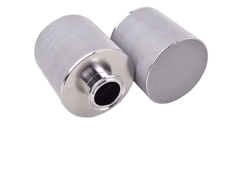
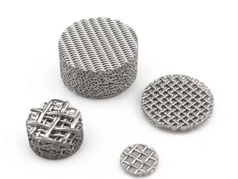
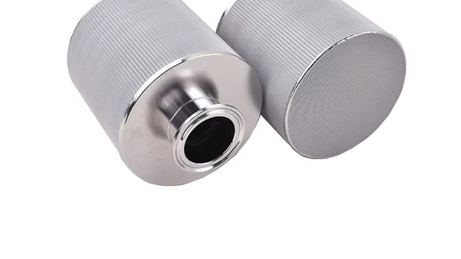
Element geometry then turns area into hardware. A bank of sintered wire mesh filter cartridges or pleated cartridges packs a large effective area into a small vessel; a set of sintered metal filter discs serves plate-and-frame and manifold arrangements. The area you calculated is the number that drives the element count, not the micron rating — a classic mistake is choosing a rating first and letting the element count follow, when the reverse order (budget the ΔP, then confirm the rating) gives a more reliable design.
Table 2 — Media construction vs permeability (indicative typical ranges for sintered stainless steel media)
| Media construction | Typical rating (μm) | Typical permeability (×10⁻¹³ m²) | Typical porosity | Notes |
|---|---|---|---|---|
| Sintered powder | 0.5–40 | 0.5–50 | 25–35% | Highest ΔP per micron; good for fine filtration |
| Five-layer sintered mesh | 1–100 | 10–200 | 30–40% | High flow per ΔP; strong and cleanable |
| Sintered metal fibre felt | 1–50 | 5–100 | 50–80% | High dirt capacity; lower ΔP build-up rate |
The datasheet curve describes a clean, dry, laboratory element. Real service deviates from it, and knowing how is part of sizing. The clean curve sets the starting point; the operating window is then the clean ΔP plus the ΔP that accumulates as captured solids build up. A prudent design allocates only part of the total allowable ΔP to the clean element, reserving the rest as dirt-holding headroom before the element must be regenerated or replaced.
Three corrections matter most. Viscosity is the biggest one: a process that runs at 60 °C but starts up cold can see clean ΔP climb by a factor of two or three because the cold liquid is more viscous — size for the worst-case (coldest) operating temperature, not the average. Temperature and media strength interact with the mechanical limits of the element: standard SS316L sintered media is typically rated for continuous service to roughly 400 °C, while alloy materials extend the envelope further, and higher-temperature duties change the practical ΔP limits as well — details that matter when the media runs near its high-temperature operating limits. Housing and fitting losses are also part of the real pressure balance: the element curve excludes vessel, piping and seal losses, which can add 0.1–0.3 bar in a poorly arranged housing.
The practical method is to treat the manufacturer's curve as the ideal baseline, apply a viscosity ratio for your actual fluid (multiply the plotted ΔP by μ_actual / μ_test), add housing losses, and then verify the result against the pump head available at the design flow. This is exactly the workflow used to specify elements for demanding oil, gas and petrochemical duties, where a ΔP budget that is off by a few tenths of a bar can mean re-pumping the whole filter package.
A related subtlety: when pleated constructions are an option, they multiply the effective area per element and can hold a fixed ΔP budget with far fewer elements — worth evaluating whenever space or vessel size is constrained by a pleated filter cartridge.
What is a typical pressure drop across a clean sintered metal filter element? For liquid service, a clean 20 μm five-layer sintered mesh element typically runs 0.1–0.3 bar (10–30 kPa) at fluxes of 20–40 m³/h per m². Finer ratings (1–5 μm) run higher, typically 0.3–0.6 bar, and gas service typically sees 50–500 mbar at far higher volumetric fluxes.
How do I calculate the filter area I need for a target ΔP? Use Darcy's law: A = (μ · Q · L) / (K · ΔP), where μ is dynamic viscosity (Pa·s), Q is flow (m³/s), L is media thickness (m), K is media permeability (m²), and ΔP is the allowable clean-element pressure drop (Pa). Add a 1.5–2× safety factor on the result.
Why is my measured pressure drop higher than the manufacturer's curve? The most common causes are higher fluid viscosity than the test fluid (usually water at 20 °C), cold startup conditions, accumulated solids adding to the clean-element baseline, housing and piping losses that the curve excludes, or a flux above the datasheet test range where the Darcy relationship no longer holds.
How does viscosity affect sintered metal filter pressure drop? Pressure drop is directly proportional to viscosity. Water at 20 °C has μ ≈ 1.0 mPa·s; if your process liquid is twice as viscous, clean ΔP doubles at the same flow. Correct the datasheet curve with the ratio μ_actual / μ_test before sizing.
What flow rate per unit area should I design for? For sintered metal media in liquid service, 10–50 m³/h per m² is a common design range, with finer ratings at the low end. In gas service, fluxes of 500–1500 Nm³/h per m² are typical. Exceeding these ranges pushes the element into a high-ΔP regime where sizing errors compound.
Pressure drop is not an afterthought — it is the design variable that connects micron rating, media area, and pump cost. When the arithmetic above points to a specific element count, the next step is confirming it against a real datasheet. KAIFIL manufactures sintered metal filter elements and sintered wire mesh filter cartridges in custom sizes and ratings, and our engineers will help you read the curves, set the ΔP budget, and size the element bank for your exact duty. Contact KAIFIL with your flow rate, operating temperature, viscosity, and target pressure drop, and get a quote with the area, element count, and clean-ΔP calculation already done.
Cartridges / tubes / cylinders / cones for reusable high-strength filtration elements, supplied to drawing with material, size and packing details confirmed at RFQ stage.
Cartridges / tubes / cylinders for reusable cartridge filtration with rigid sintered mesh media, supplied to drawing with material, size and packing details confirmed at RFQ stage.
Rigid five-layer sintered wire mesh laminate for cleanable precision filtration and custom elements.
Send drawings, dimensions, material, environment or operating conditions, and we will help confirm the right specification.
Uploaded reference files are included with the inquiry. For larger CAD packages, reply to the confirmation email or send them here:
Our team typically replies within 24 business hours.